Back to builds

Build Log

Santa Maria

in progressScale: 1:65Amati

Detailed three‑masted carrack from the Age of Discovery, the flagship of Christopher Columbus’s first Atlantic expedition

Santa Maria

Historical Background

Santa Maria, originally known as La Gallega, was the largest of the three ships in Columbus’s first voyage and the only carrack among two lighter caravels, Niña and Pinta. Built as a robust merchant nao on the Spanish Atlantic coast, she was owned and commanded by Juan de la Cosa and adapted for a risky westward crossing into largely unknown waters. Her high fore and aft castles, three masts and capacious hull made her suitable for long ocean passages with provisions and crew, turning a typical trading vessel into the main command ship of a pioneering transatlantic expedition.

Under Columbus’s leadership, Santa Maria led the small fleet out of Palos de la Frontera and across the Atlantic, later becoming a symbol of the beginning of sustained European expansion into the Americas. Near the coast of Hispaniola she ran aground and was lost, and her timbers were used to build the small fort of Navidad, while the remaining ships returned to Spain, leaving Santa Maria forever tied to the dramatic opening chapter of the Age of Exploration.

Build Log

Part 1

23.04.2026

Unboxing

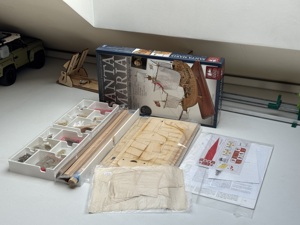
This model was a gift from a colleague, and I promised it would be next in line for building. The queue took over a year to get through—but I’m keeping my word. Thanks again, and let’s start a new project!

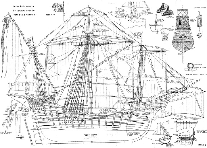
The kit is standard for Amati: good-quality wood and decent rigging thread. The boat, as usual, is a bit of a letdown—it’s an aluminum casting, so I’ll have to think about what to do with it. There are only two sheets of plans, but the model isn’t complicated, so that’s more than enough.

↑ Back to all parts

Part 2

26.05.2026

Hull

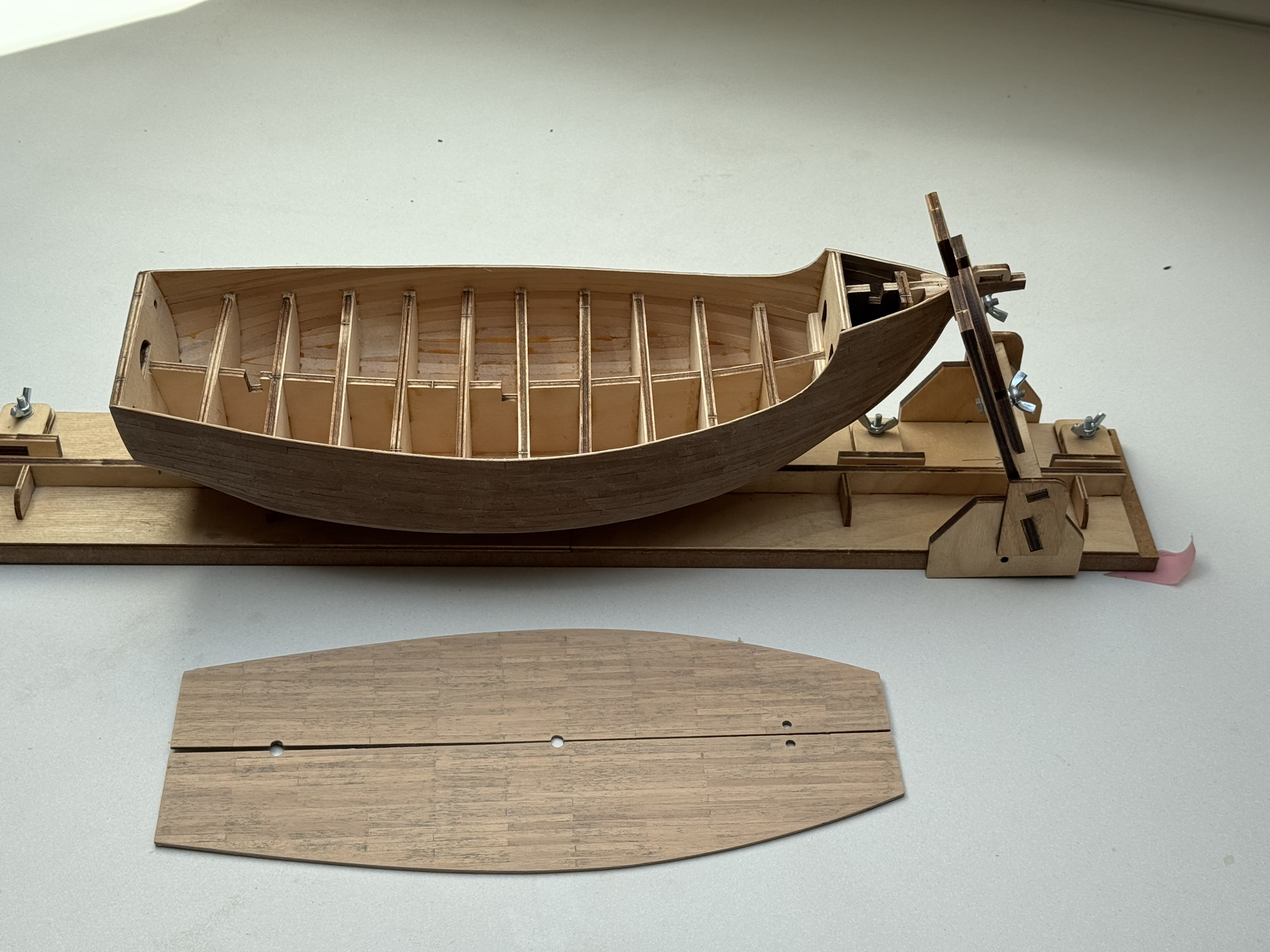
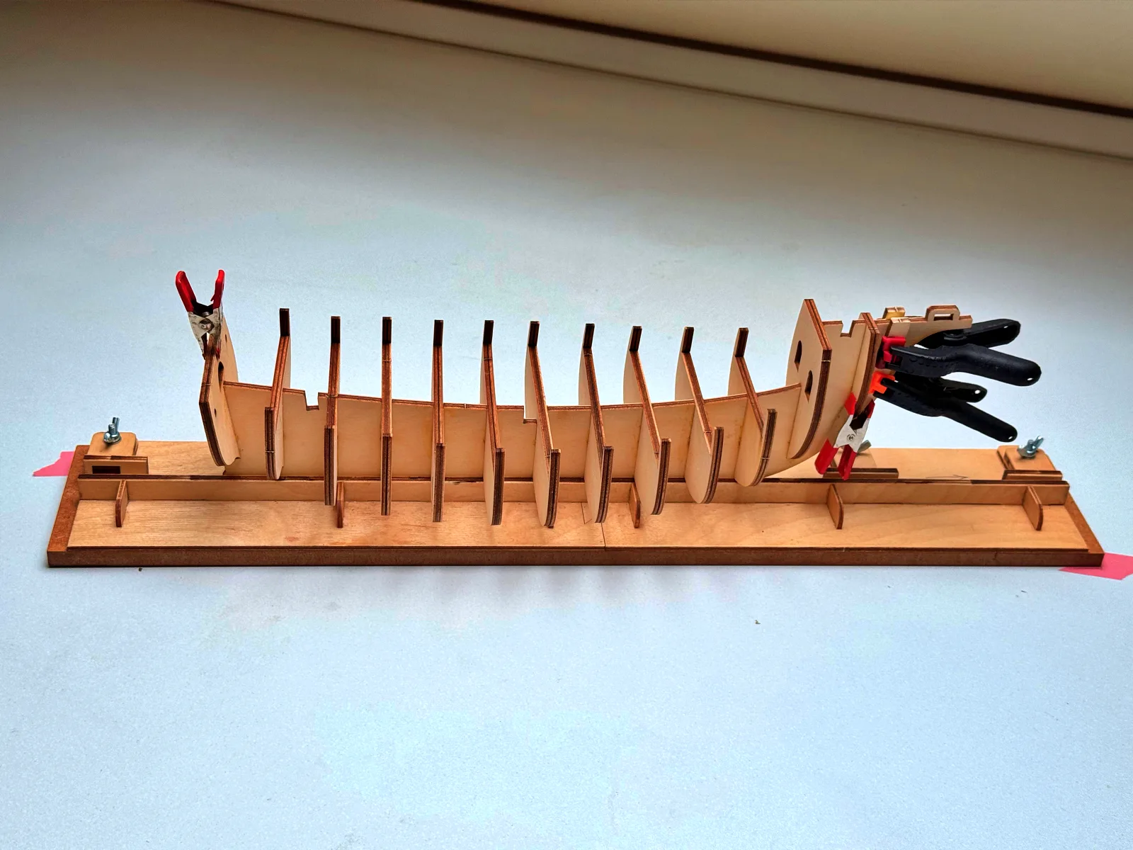
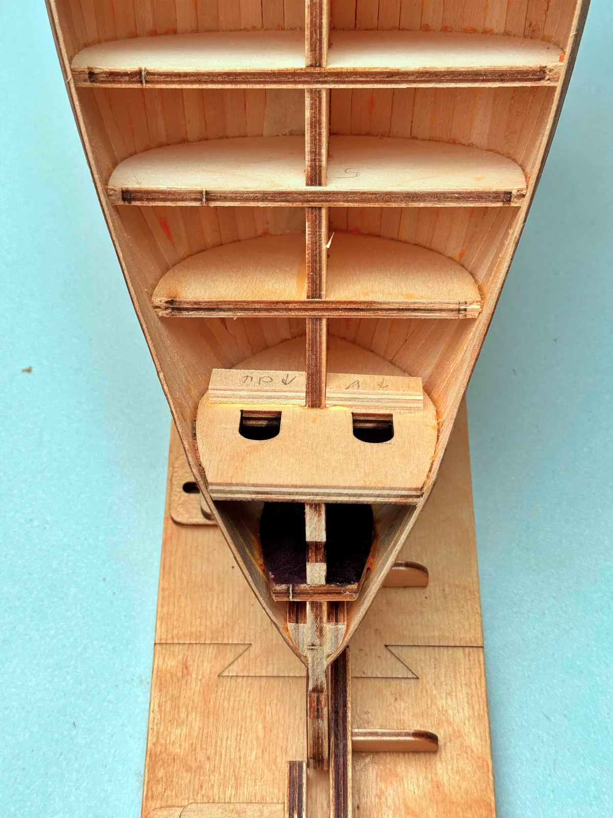
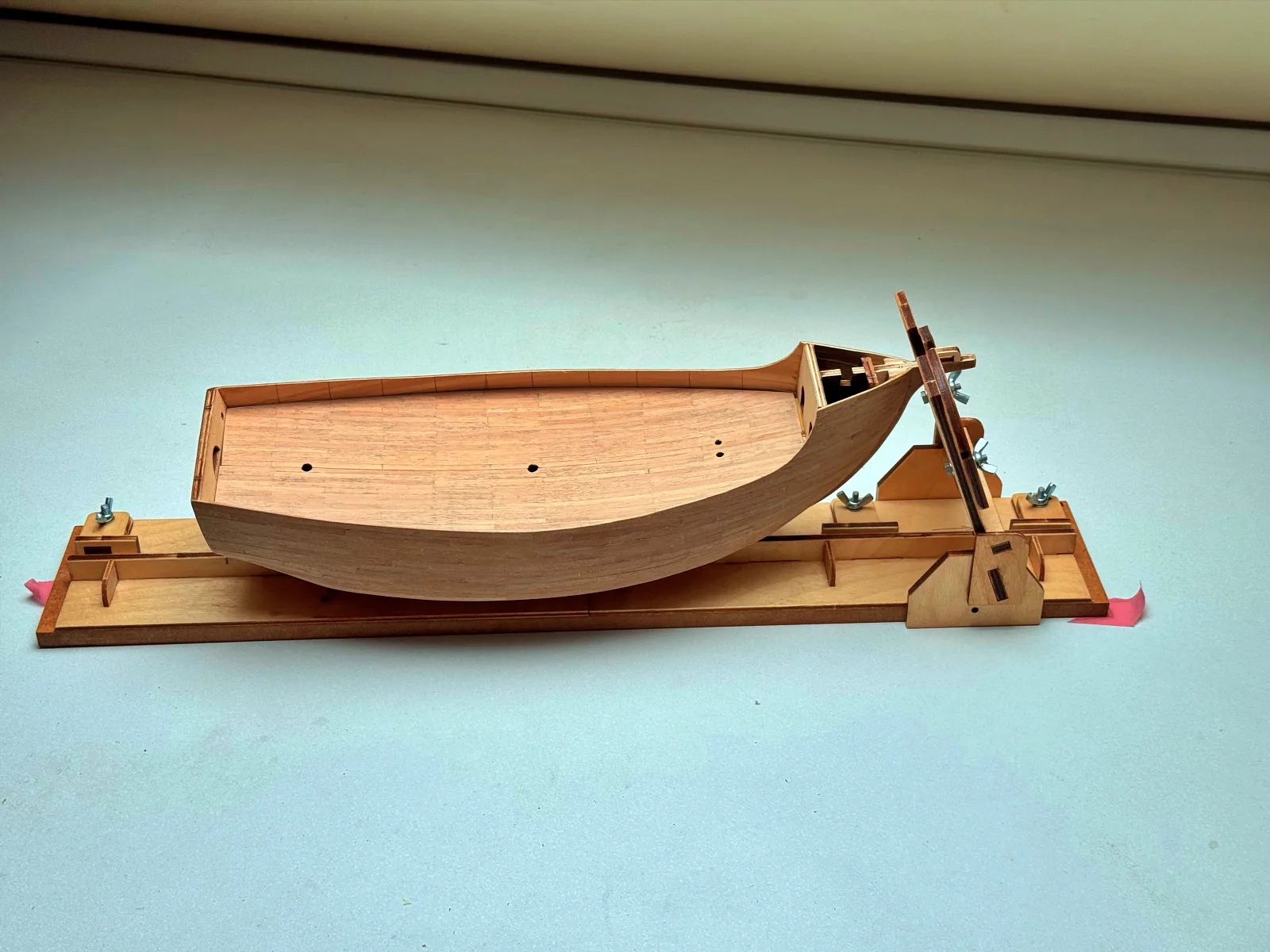
The build begins with assembling the hull frame from 5 mm plywood. There are relatively few bulkheads, so the process is straightforward and does not take much time. However, this stage is critical when it comes to maintaining proper alignment—any distortion introduced here will be nearly impossible to correct later. From experience, it is highly beneficial to fill the space between the forward bulkheads with balsa blocks, which greatly simplifies the planking process down the line. Once the structure is in place, the bulkheads are carefully shaped to ensure smooth hull lines, preparing the surface for the first layer of planking.

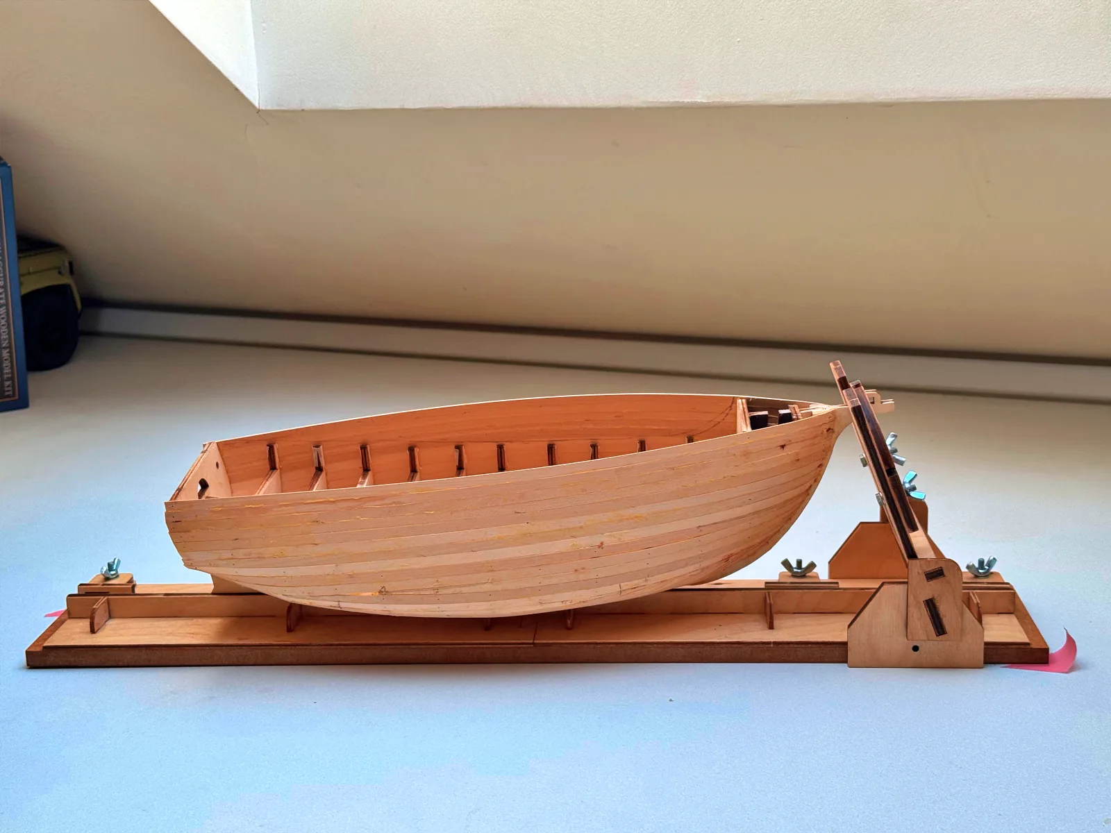
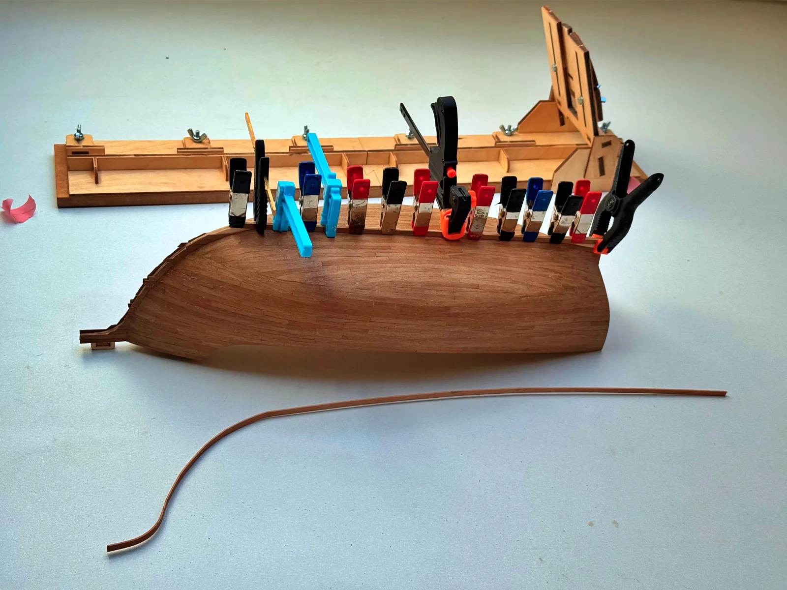
The first planking layer is done using relatively wide and thick limewood strips (7×1.5 mm). Its purpose is to create a solid base for the final planking. Due to the pronounced deck camber and the high bow, some planks in the forward section are attached primarily to adjacent planks rather than directly to bulkheads. Small gaps and the use of temporary nails are acceptable at this stage, as the surface will later be sanded, filled, and sanded again. Any excess planking is carefully trimmed according to the plans to achieve the correct hull shape.

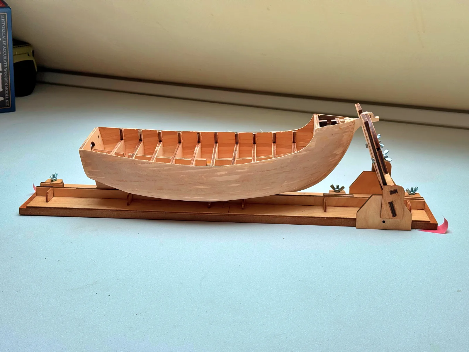
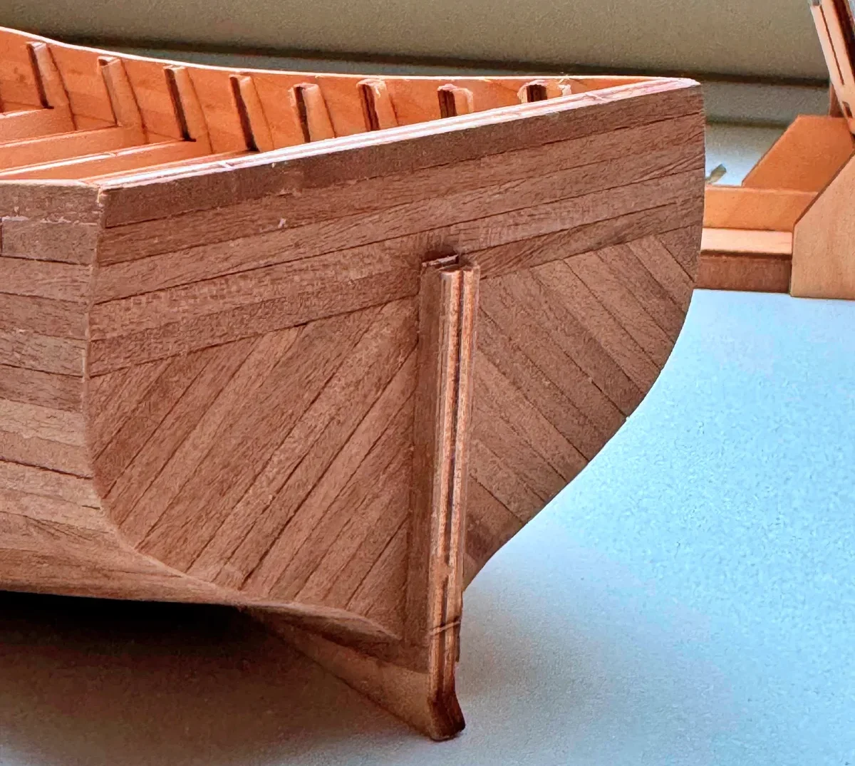
The second, finish planking layer is a more delicate and precise process. It is applied using individual planks scaled to approximately four meters in real length, which aligns well with historical shipbuilding practices. Toward the bow, the planks are gradually tapered, and in some areas, stealers are introduced to avoid reducing the planks into overly narrow strips. This approach helps maintain a realistic and visually consistent planking pattern.

With the second layer complete, the main hull structure can be considered finished. The surface is now ready for further detailing, and the next steps include laying the deck and constructing the bow and stern superstructures, which will bring the model closer to its final appearance.

↑ Back to all parts

Part 3

04.07.2026

Deck and armament

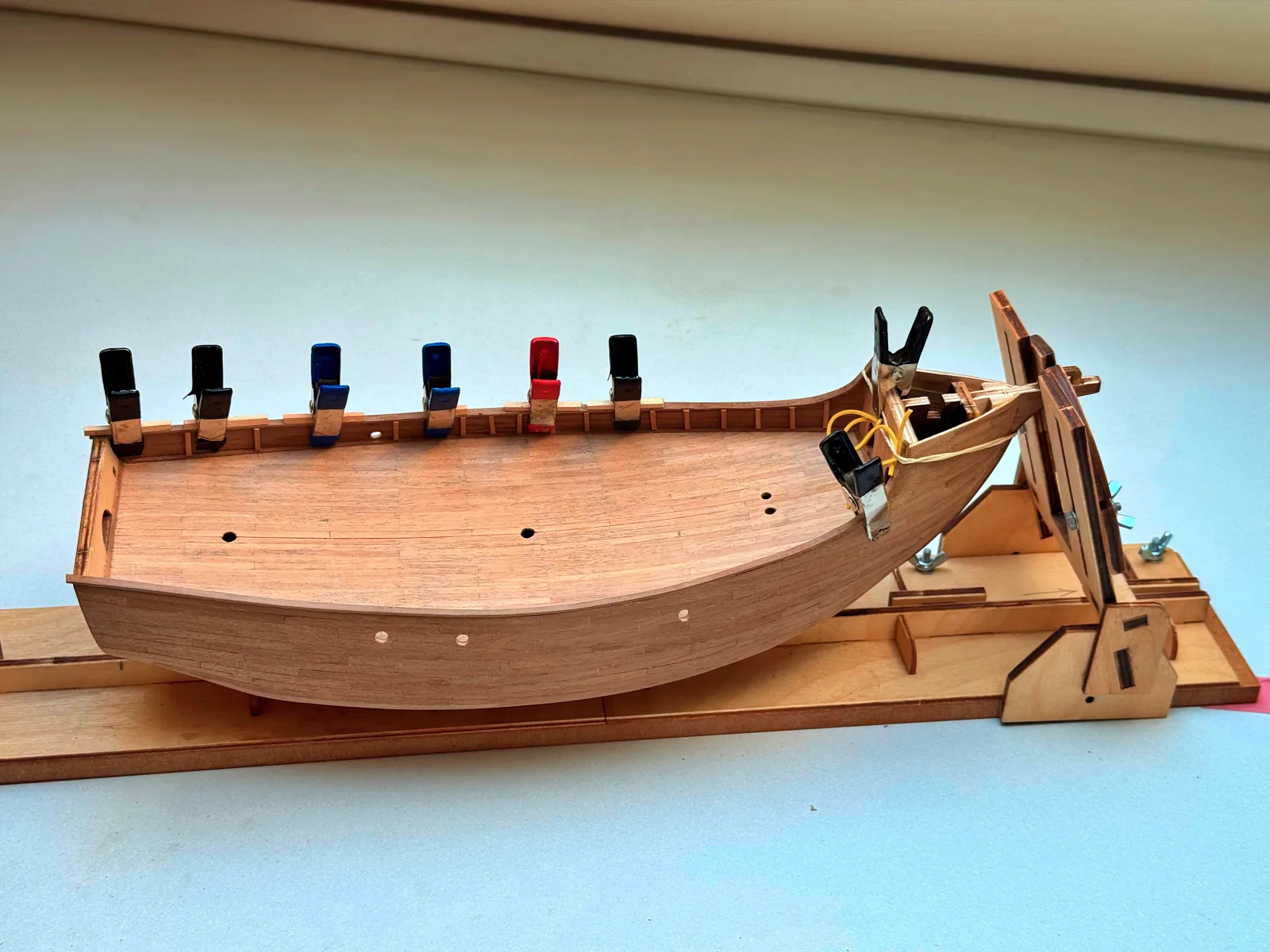
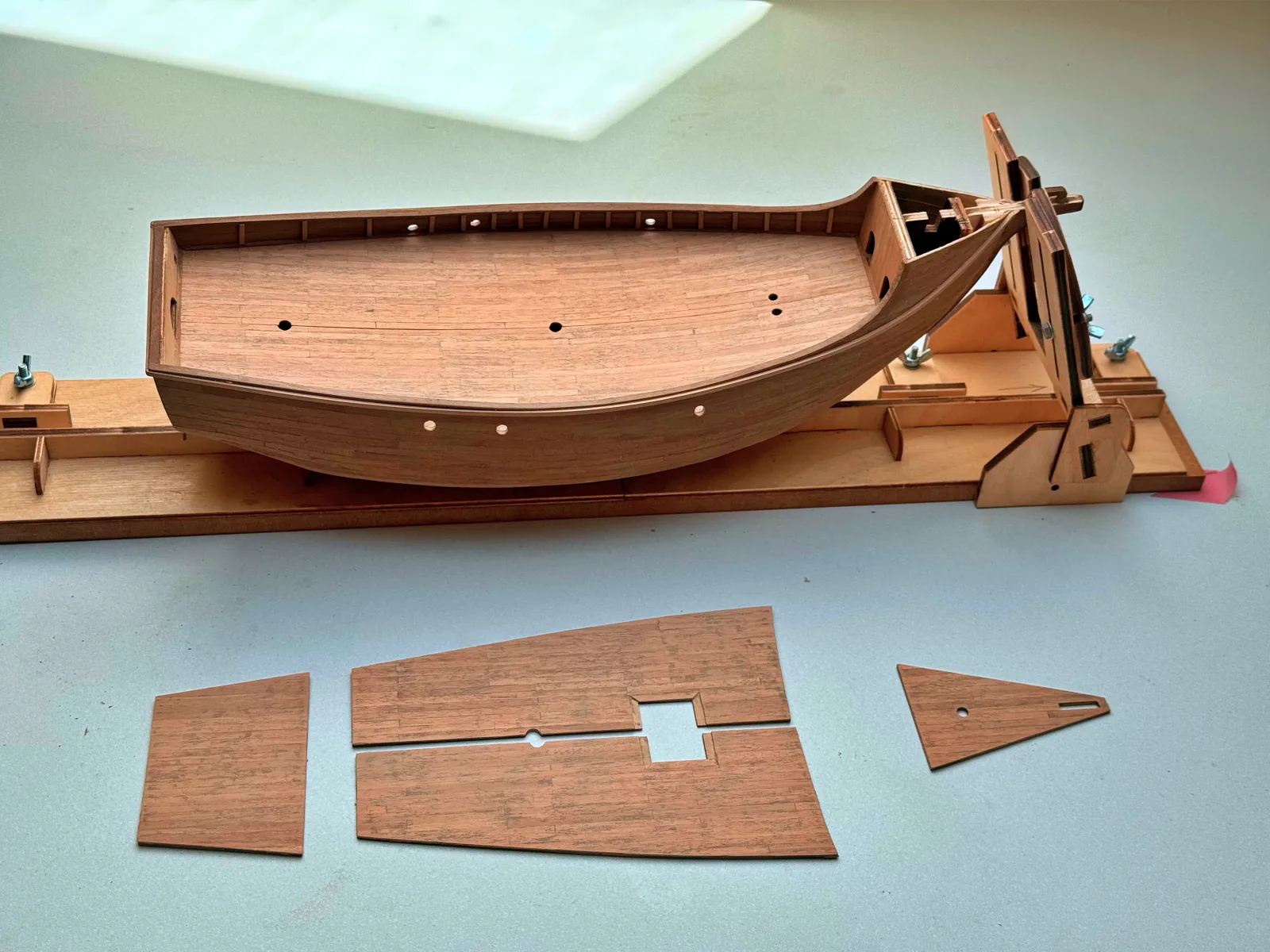
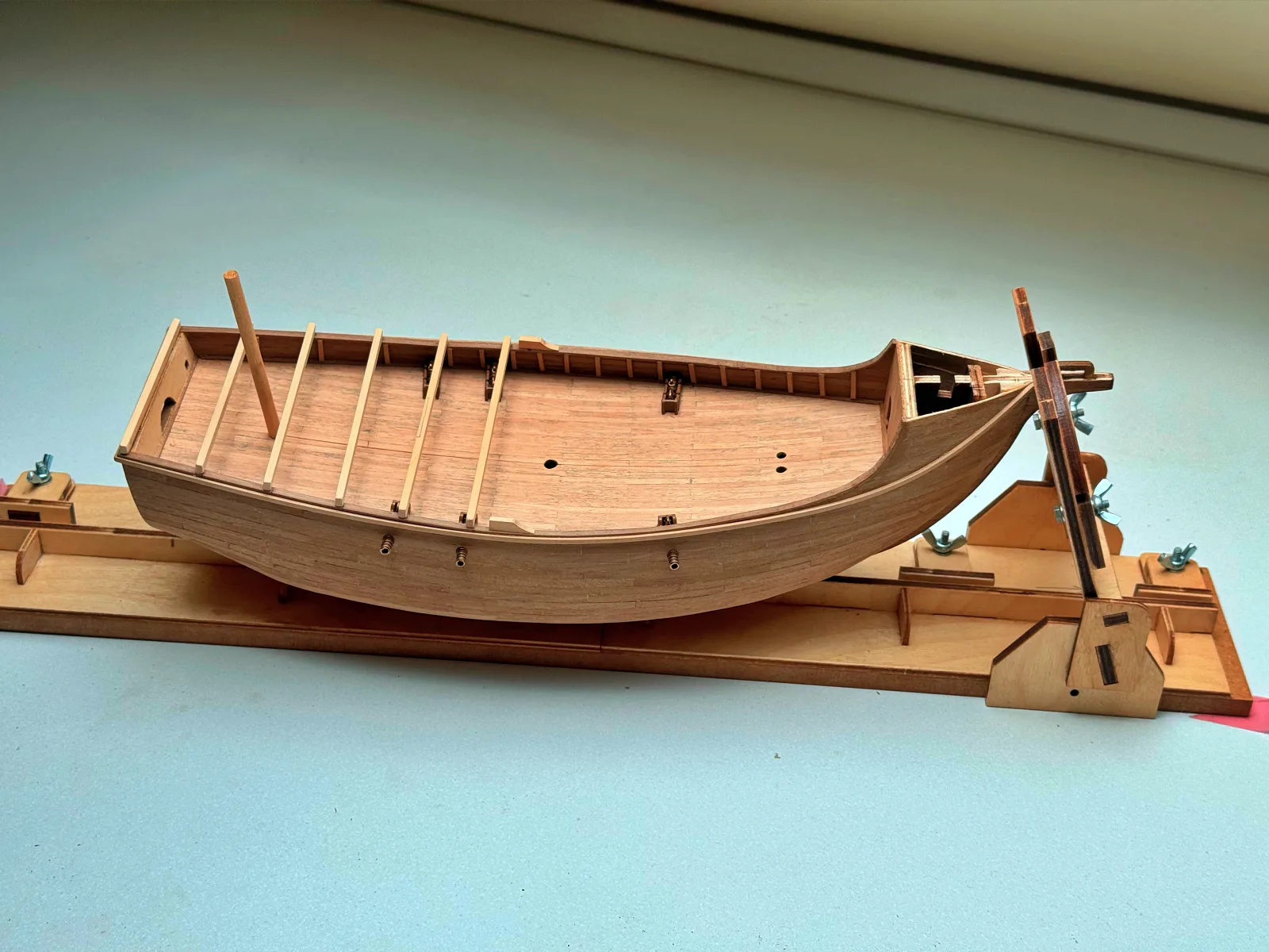
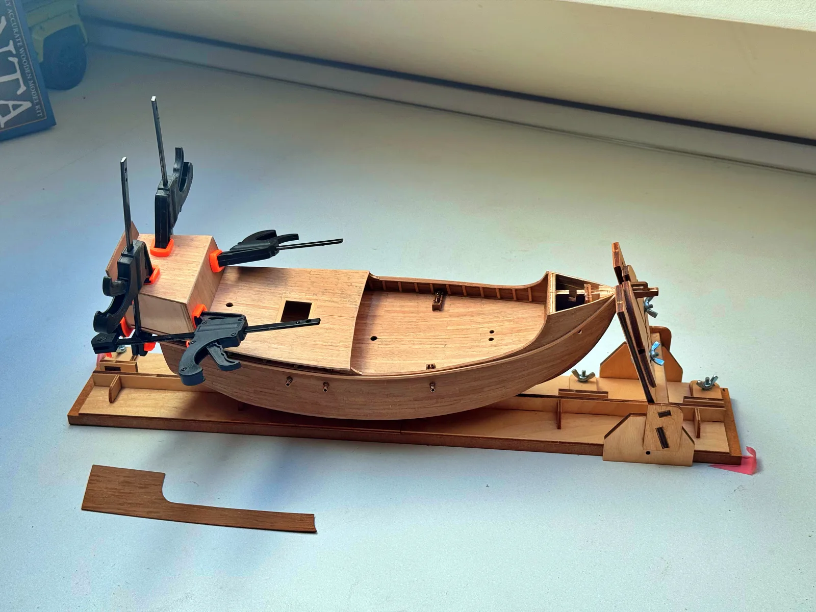
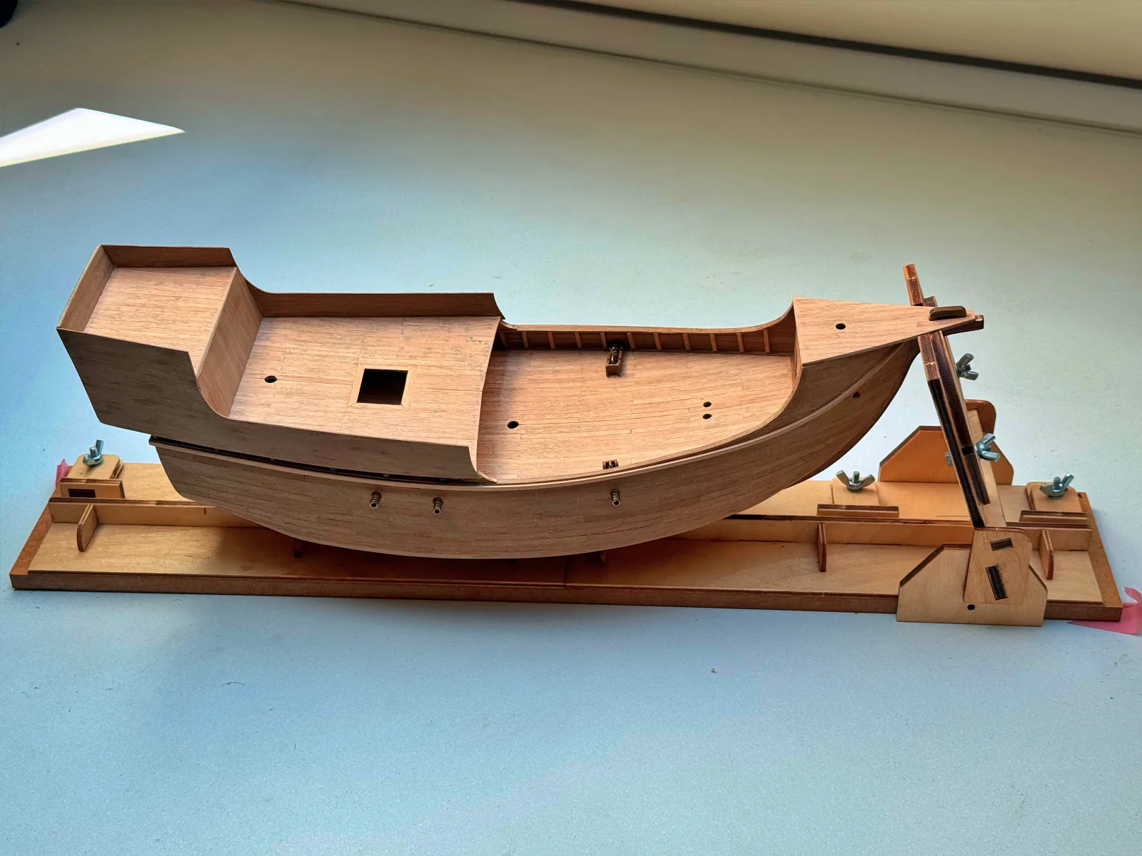
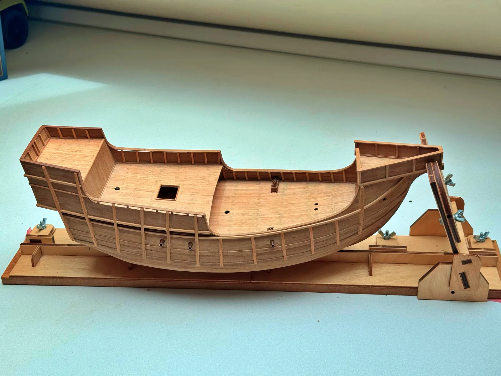
With the main hull structure complete, it is time to move on to the deck. Santa Maria, modelled here as a late fifteenth‑century carrack, is characterised by pronounced fore and aft castles, so in addition to the main deck I needed to build the quarterdeck, which takes up roughly half the footprint of the main deck, as well as the smaller platforms of the fore and stern superstructures.

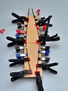
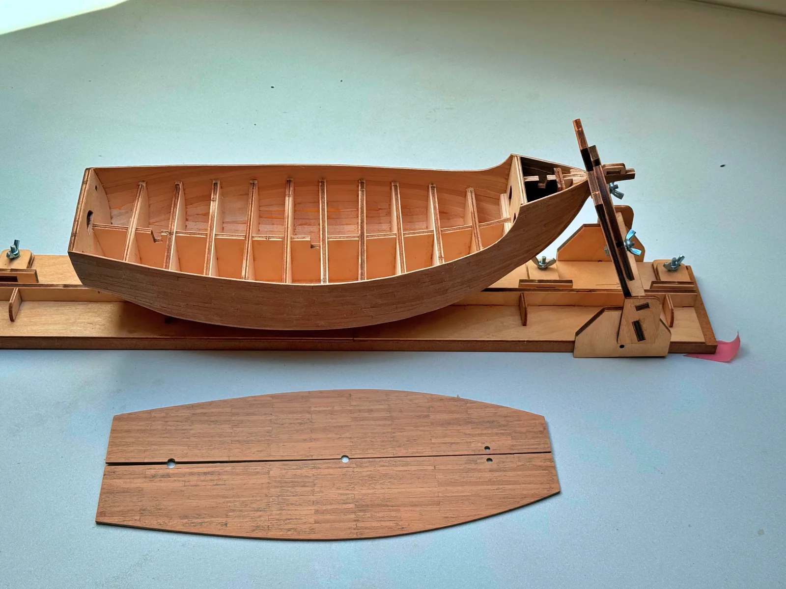
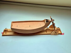
The deck planking is laid from individual 1 mm thick strips onto a 1 mm plywood base. The deck comes in two halves that have to be joined, so it is critical to align the planks along the centreline seam to keep the joint invisible on the finished model.
Once the blank is planked, the deck is trimmed to its final outline directly against the hull, because the actual dimensions can differ slightly from the printed plans, and even a small mismatch will be noticeable. Minor gaps will be hidden later by the waterway, but the more accurately the deck fits now, the better.
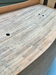
For filling the plank seams this time I decided to experiment. Instead of my usual approach, I used a resin‑based furniture repair paste: it is rubbed into the rough planking, the excess is immediately wiped off with a paper towel, and then the whole deck is sanded smooth. The end result is up to you to judge.
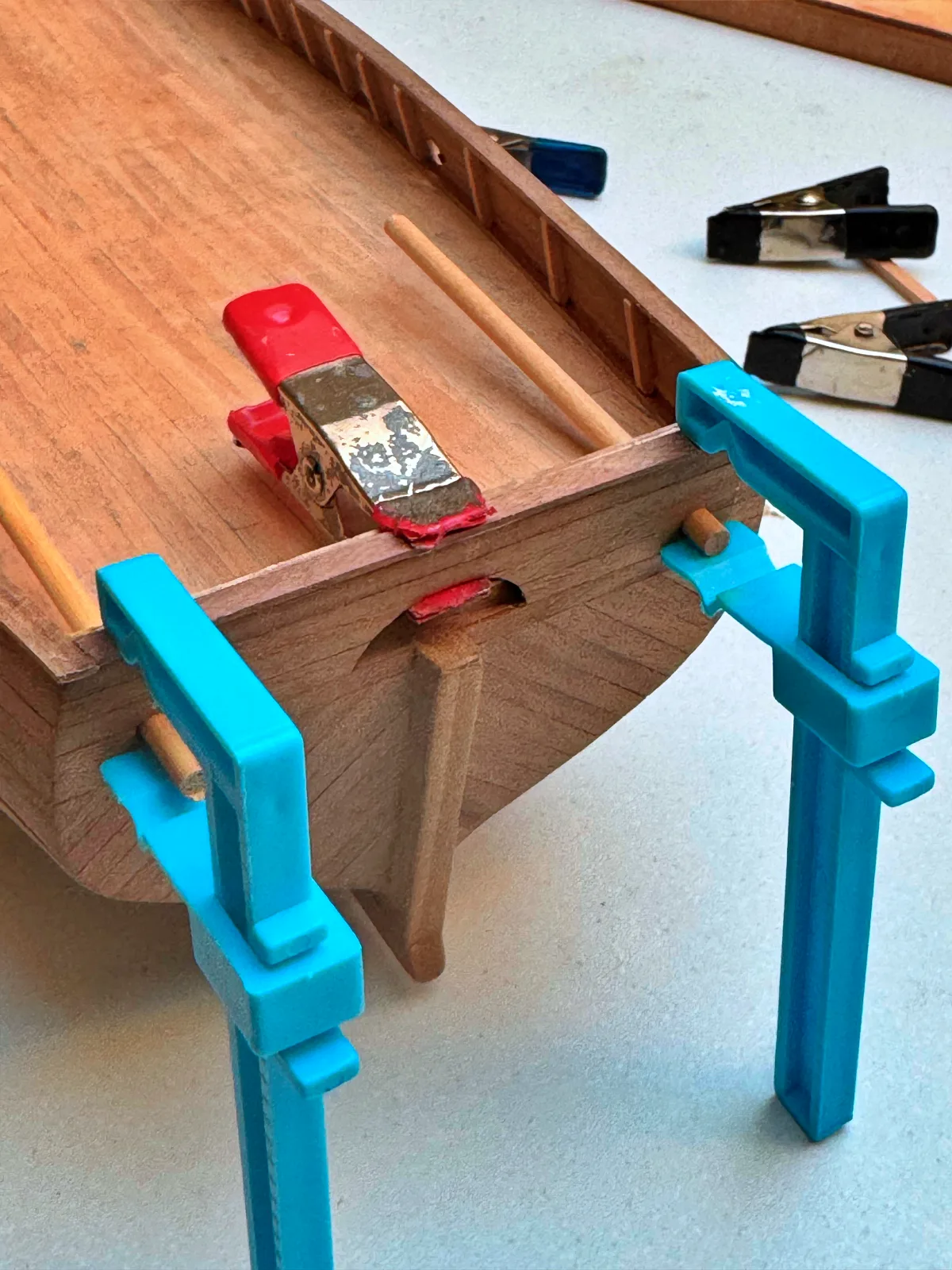
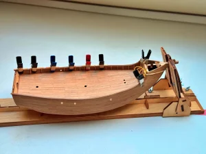
The main deck is glued in first. After that, I install the waterway from two 1×1 mm strips, which is a very convenient solution because it avoids bending a wider strip across its wide face. Then the caprail goes on. This piece, however, requires bending in two directions: across the beam and in height. I first form the horizontal curve across the wide side and let it dry completely, and only then, using water and a heat tool, very carefully bend it vertically.
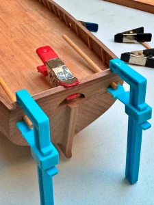
Before laying the quarterdeck planking, the beams need to be installed. Here the first surprise appears: the kit provides these parts in limewood. The beams remain visible on the finished model, at least partially, so it would have been more appropriate to include walnut stock in the box. I solved it with stain instead.
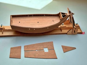
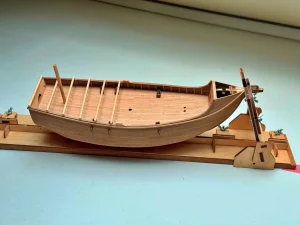
Apart from this nuance, all deck sections went in without any major problems.

For the nail simulation I went with a proven method and skipped further experiments. I drill 0.6 mm holes (a pair at the end of each plank), insert thin wire pieces and sand them flush.

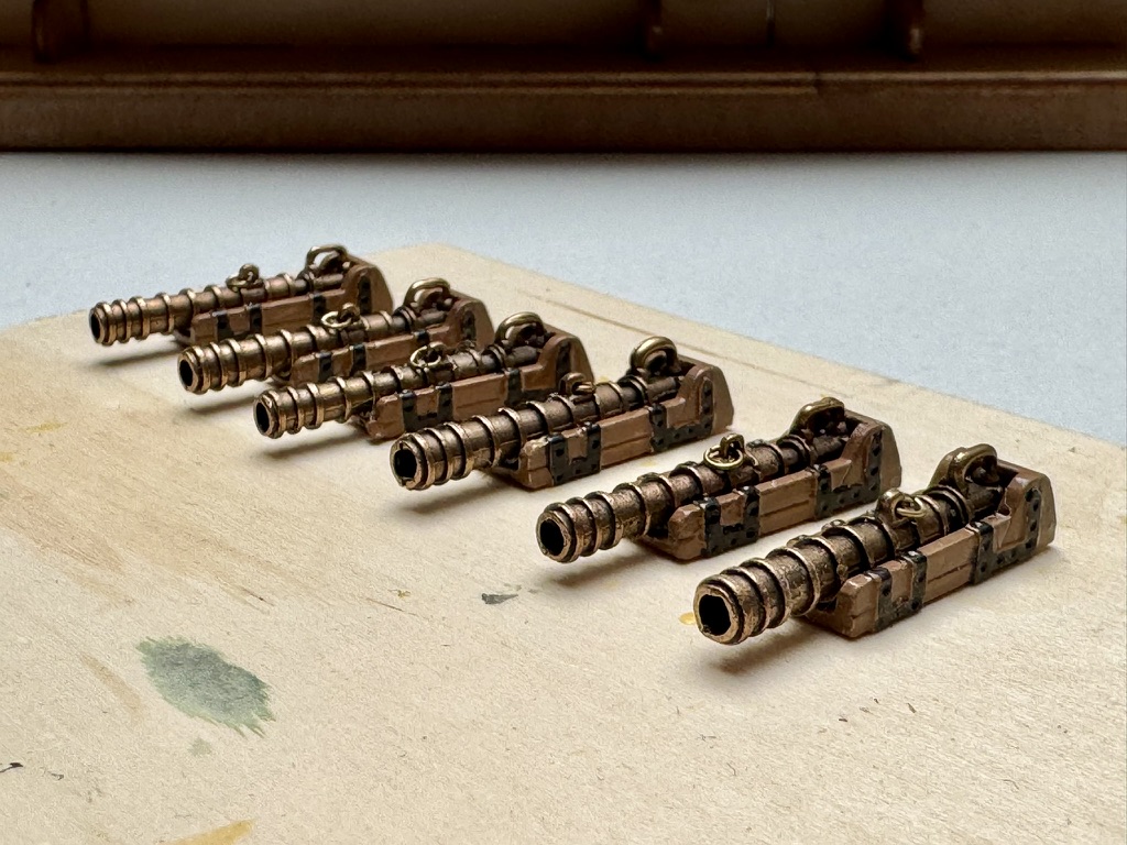
The guns are a story of their own. The main problem is that nobody knows for certain what the ship actually looked like. Many modern reconstructions show four bombards grouped around the quarterdeck area, but it is unclear whether they were placed directly on the quarterdeck or on the main deck beneath it. Why the Amati kit includes six such guns is also open to speculation, but given how little is known about the ship’s real layout and armament, I consider this acceptable and decided not to modify the kit.
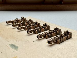
Once the deck planking is done, I install the stanchions for the bulwarks (and the bulwarks themselves), then bend and fit the caprails on the quarterdeck and on the castles.
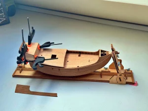
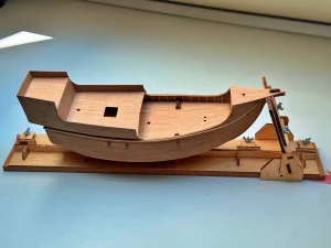
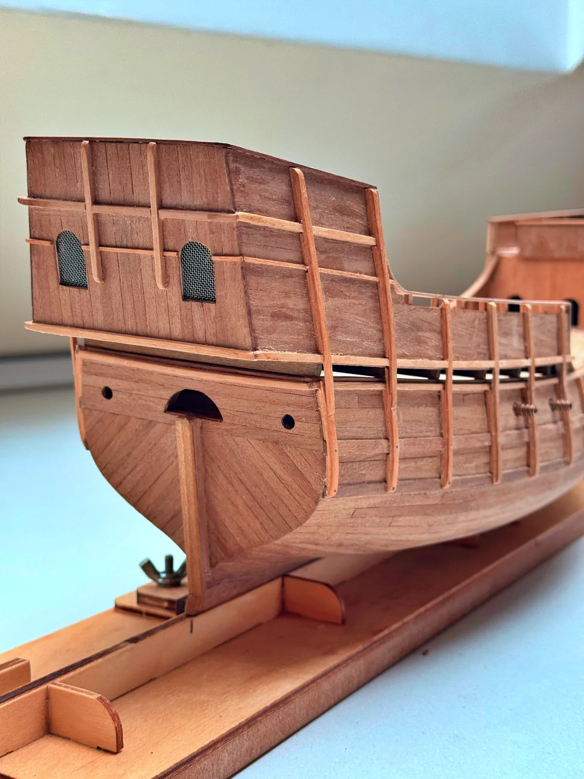
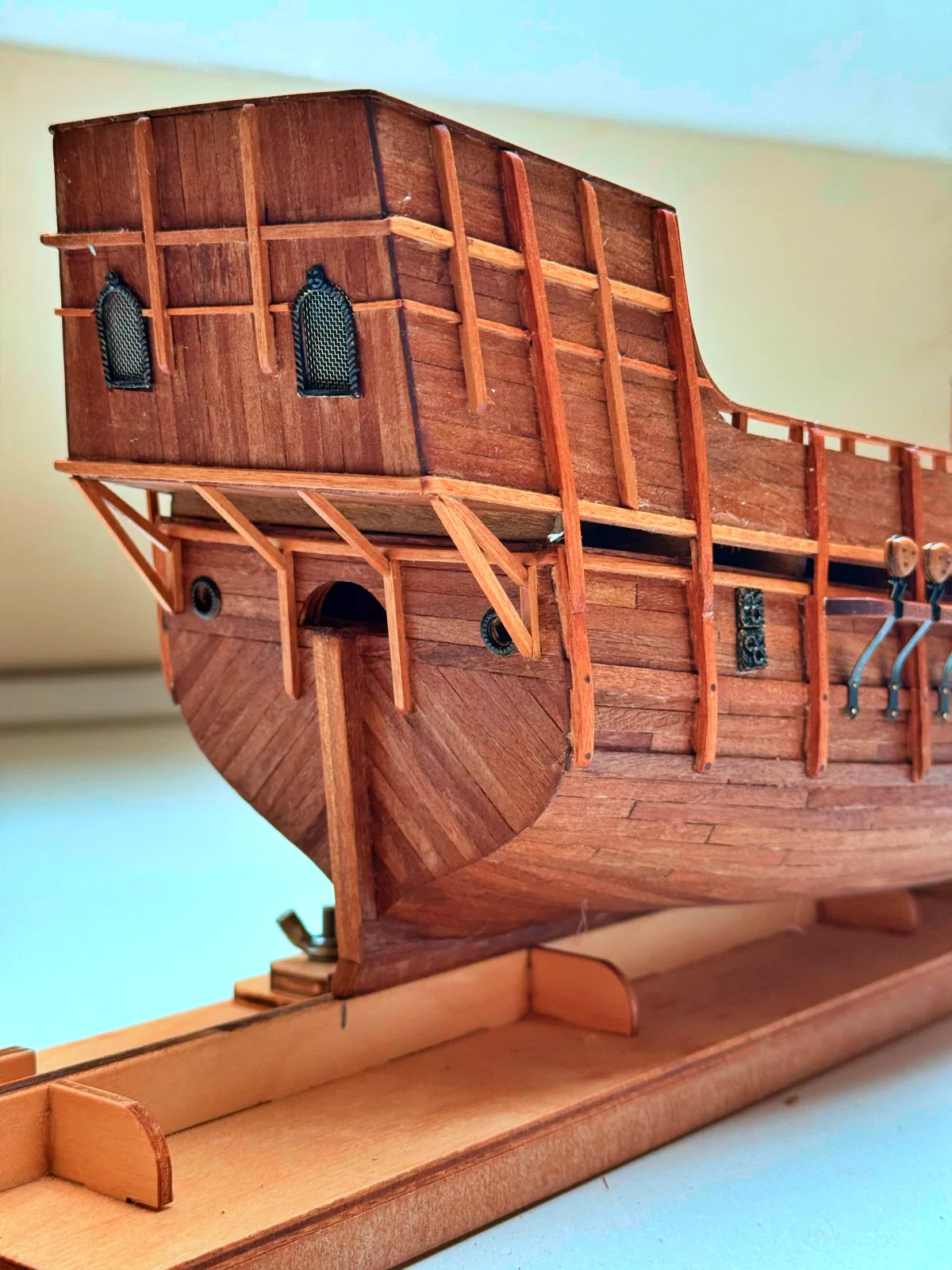
With all decks, bulwarks, and cap rails now in place, attention returns to the hull. At this stage, the remaining wales must be completed and properly faired along the hull. These heavy longitudinal strakes are critical both structurally and visually, defining the ship’s sheer and reinforcing the planking.
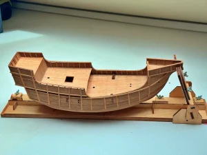
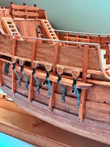
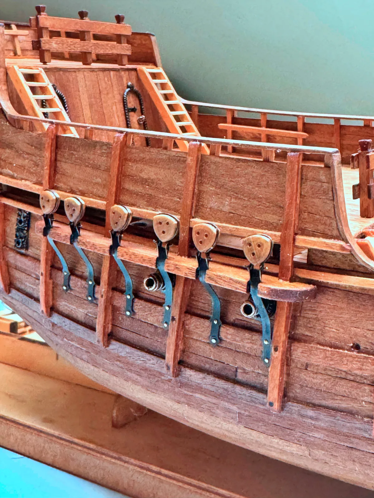
Following this, install the vertical timbers—fenders (skids)—spaced along the hull sides. These elements, characteristic of many vessels of the period, served to protect the planking from abrasion during contact with piers or alongside other ships.
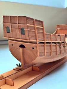
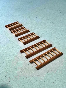
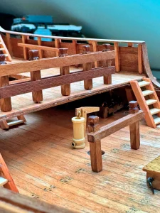
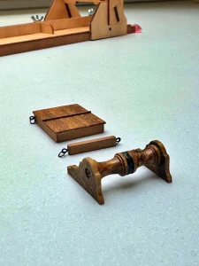
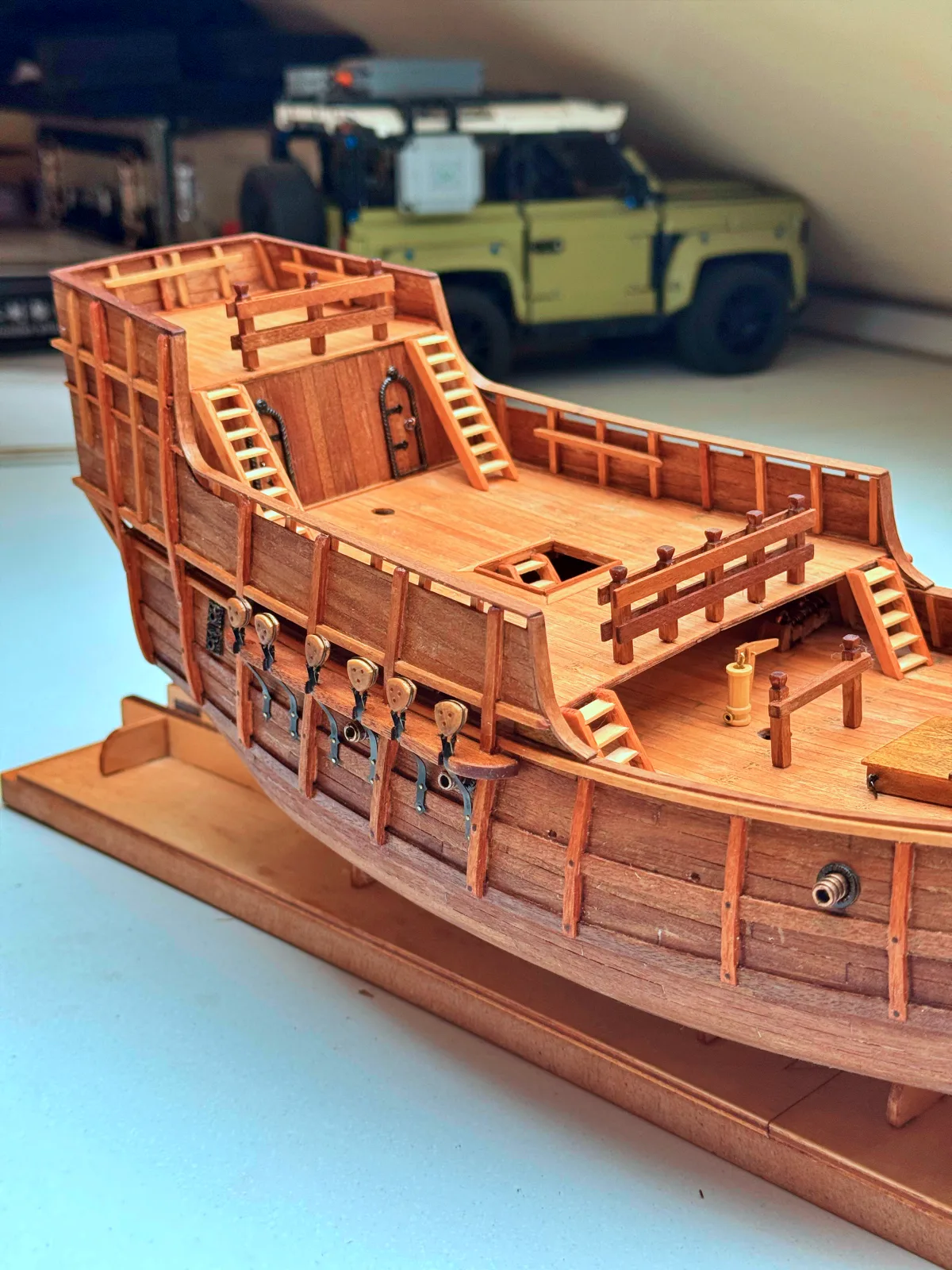
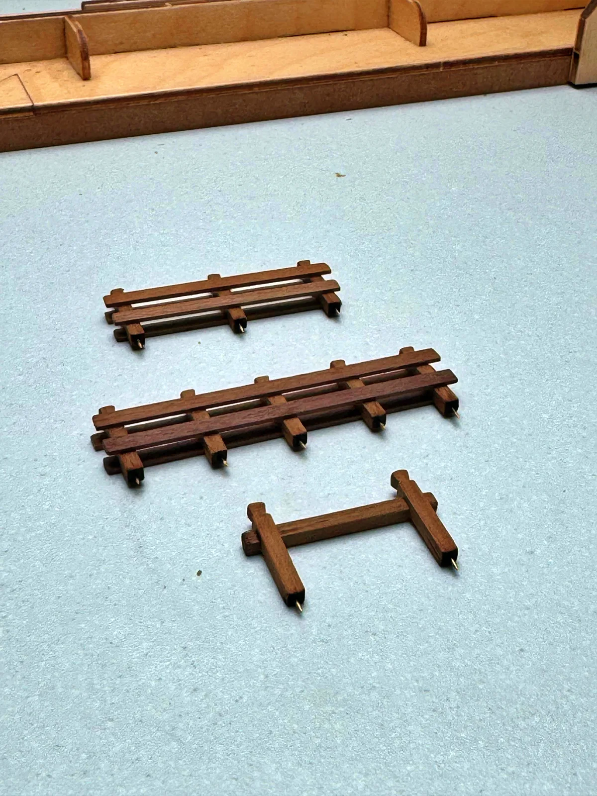
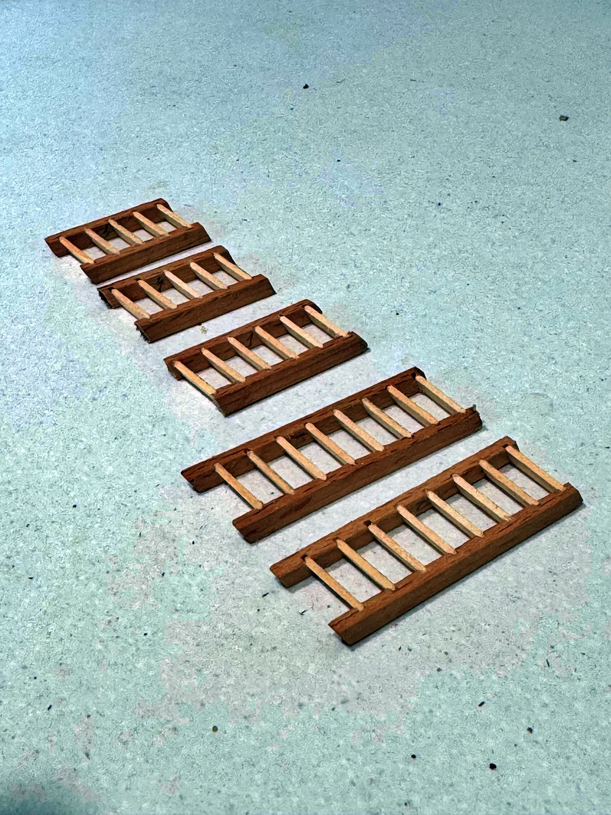
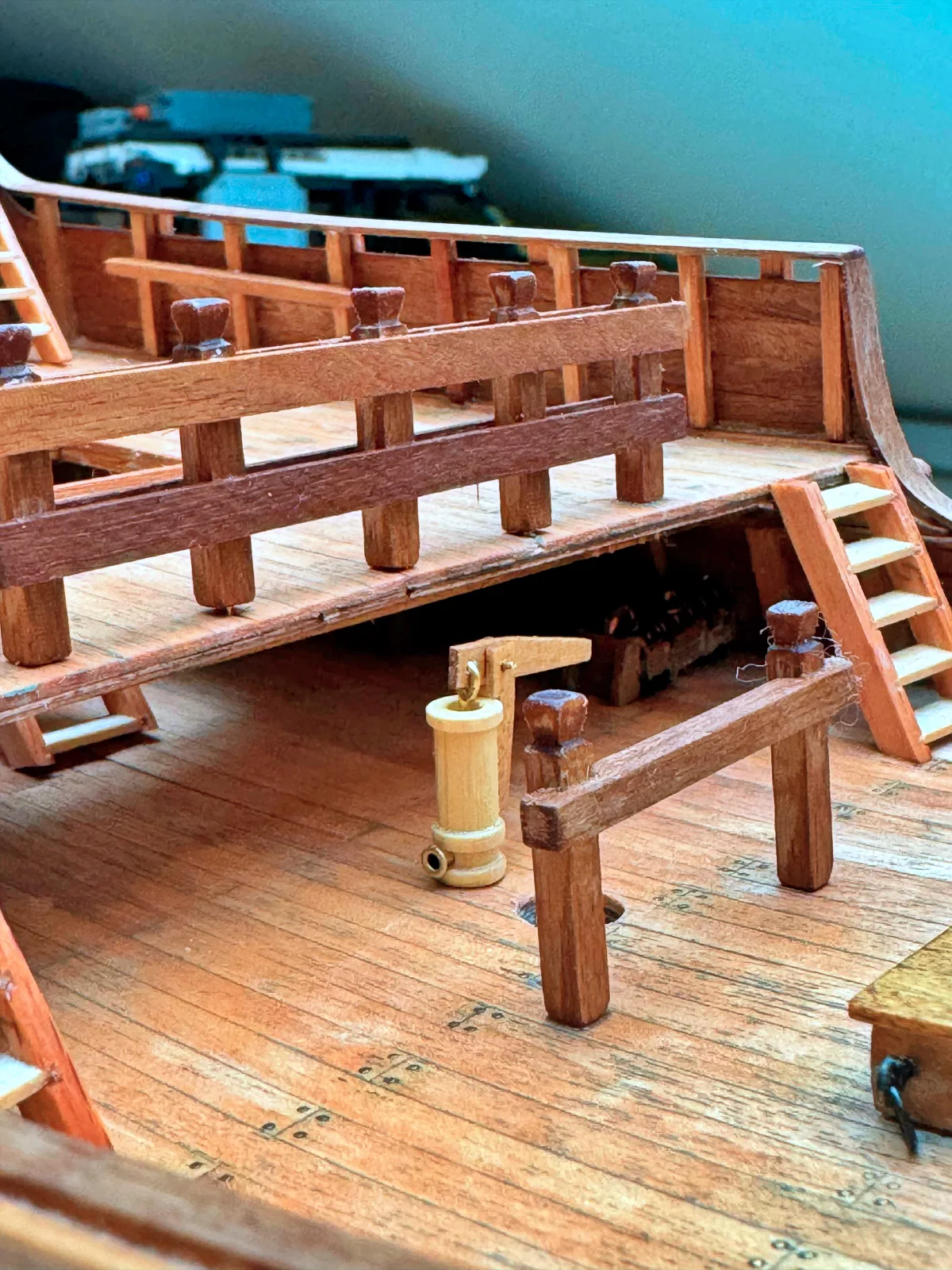
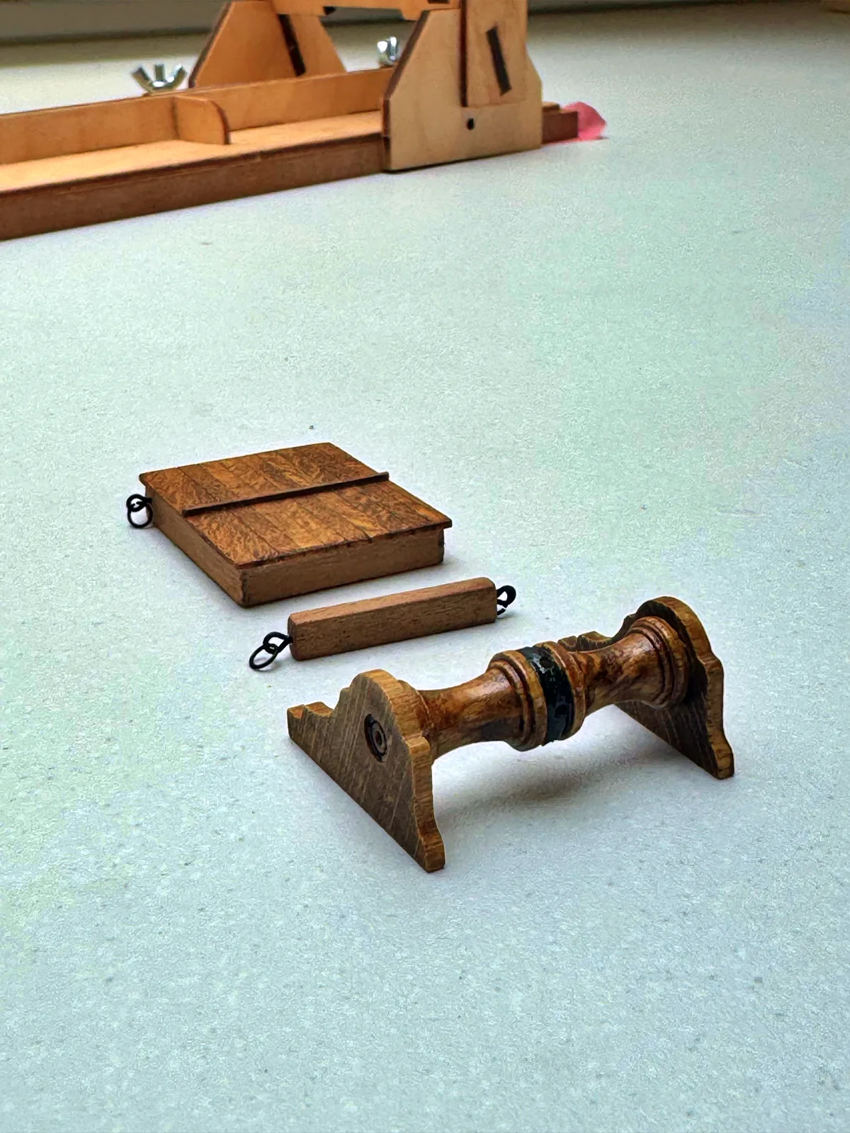
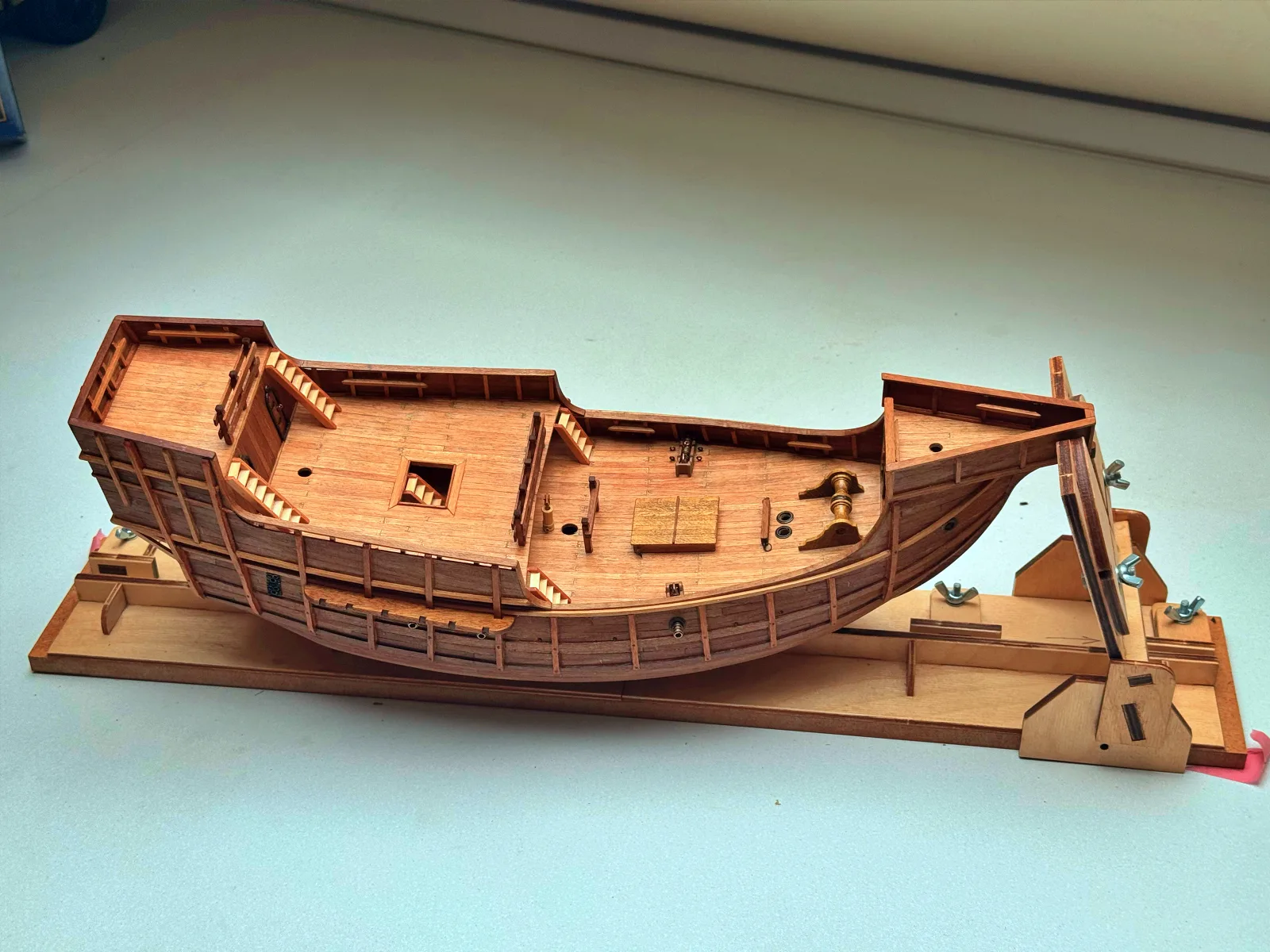
With that, the deck and hull  can be considered complete. I add the smaller details: ladders, the windlass, coamings and hatches, bitts, belaying rails and cleats for the future rigging.
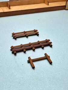
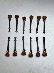
At this stage I also blacken and install all brass fittings. On the real ship there would have been no decorative copper or bronze frames around openings; such elements were made of wood, which darkened with time, so here the metal serves only as a stand‑in.
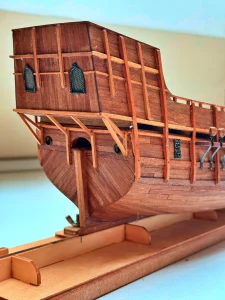
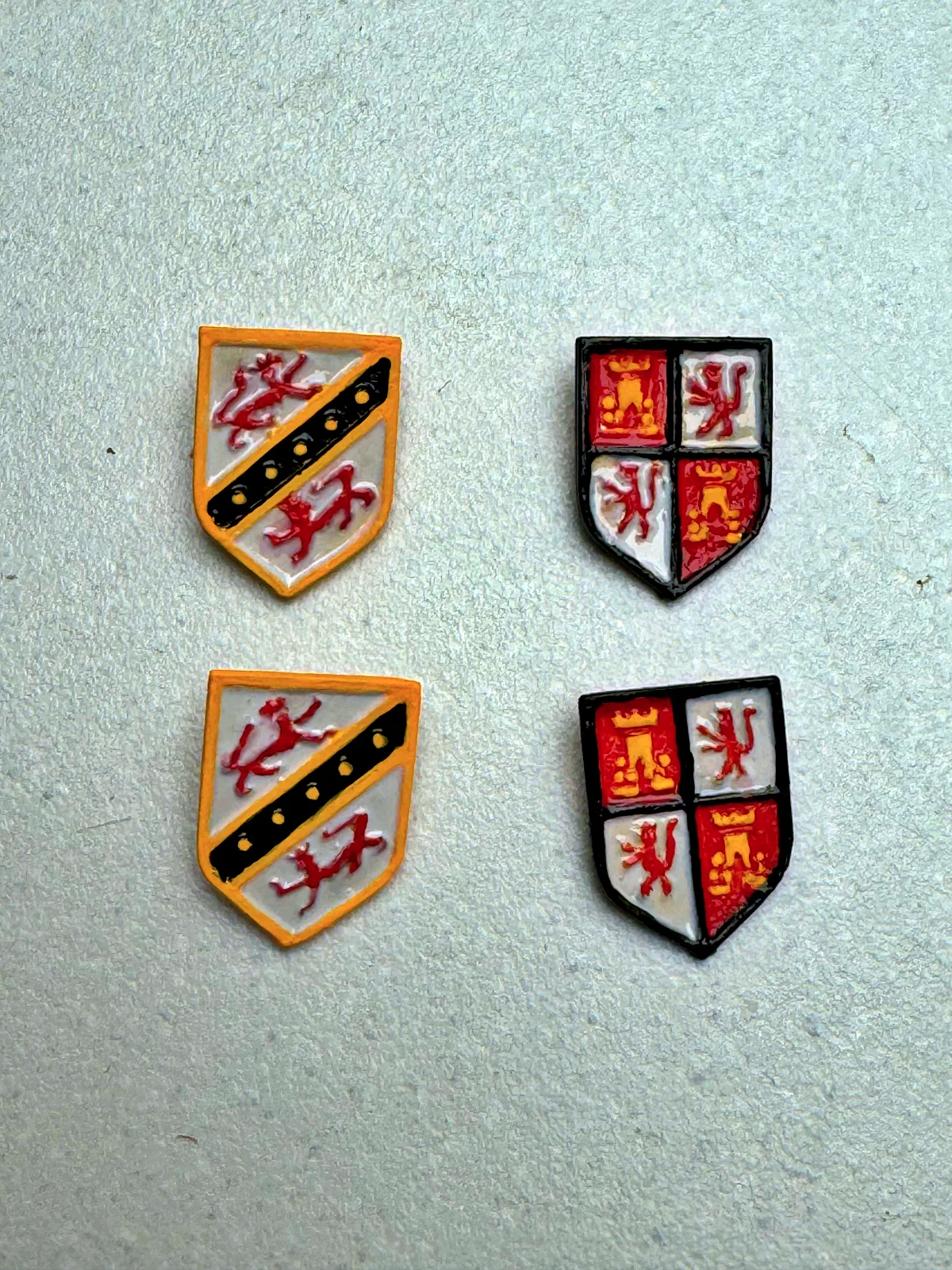
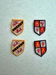
The only items that will receive colour are the shields decorating the stern superstructure — and those are a task for an artist.
With all that in place, the deck parts are oiled, and the model is ready for the next chapter: making and installing the masts and spars.
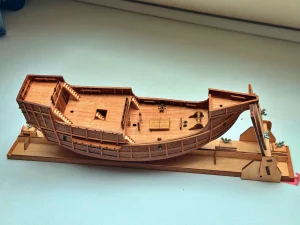
Full video of the hull building process available on YouTube channel glushkov-modelling

↑ Back to all parts

Part 4

19.09.2026

Spars and Standing Rigging

We are now moving on to the stage that truly transforms a hull into a sailing vessel: making and stepping the spars.

The spar arrangement of the Santa Maria is comparatively simple. This is partly because the highly developed sail plans of the seventeenth and eighteenth centuries were still centuries away, and partly because this model is not intended to reproduce every possible detail of the original vessel.

The kit provides a set of round limewood dowels, which must be shaped into three masts with their respective topmasts, a bowsprit, and several yards: the spritsail yard on the bowsprit, the fore yard, the main yard, the main topsail yard, and the mizzen lateen yard. The main yard and mizzen lateen yard are built-up assemblies, while the remaining yards are made from single pieces.

The first step is to turn the blanks on the lathe.

Limewood works very well and presents no real difficulties; the main task is simply to keep a close eye on the dimensions. Once the individual parts have been glued together and the top has been fitted to the mainmast, the spars need to be stained to match both the intended appearance of the prototype and the rest of the model. Walnut would probably have been a better choice for the spars, but we work with the materials available in the kit.

After staining comes the preparation of the standing-rigging fittings. This includes fitting wooldings to the mainmast, main yard, and mizzen lateen yard, as well as stropping and fitting the necessary blocks to the mastheads, topmasts, and yards. It is far more convenient to do this before the masts are stepped in the hull.

Now it is time to step the spars. As usual, we work from bow to stern. The bowsprit comes first and is secured to the stem by a gammoning. It is followed by the foremast, stepped with a slight rake forward, then the mainmast, and finally the mizzenmast, which is raked slightly aft.

With the masts fixed in the hull, it is time to make and fit the stays: the principal items of standing rigging that support the masts in the fore-and-aft direction. The eye of the mainstay is served and fitted with a mouse — a raised stop that prevents the eye from tightening into a noose around the masthead and protects the stay from chafing. On the model, the stays of the foremast and mizzenmast are made without mice because of the scale.

Once the stays are in place, we can move on to the shrouds — probably the most visually prominent elements of the standing rigging. They support the masts laterally and are fitted in pairs. The eyes of the foremost starboard pair are placed over the masthead first, followed by the corresponding port pair, with the remaining pairs fitted progressively from forward to aft. The eyes of the main shrouds are served.

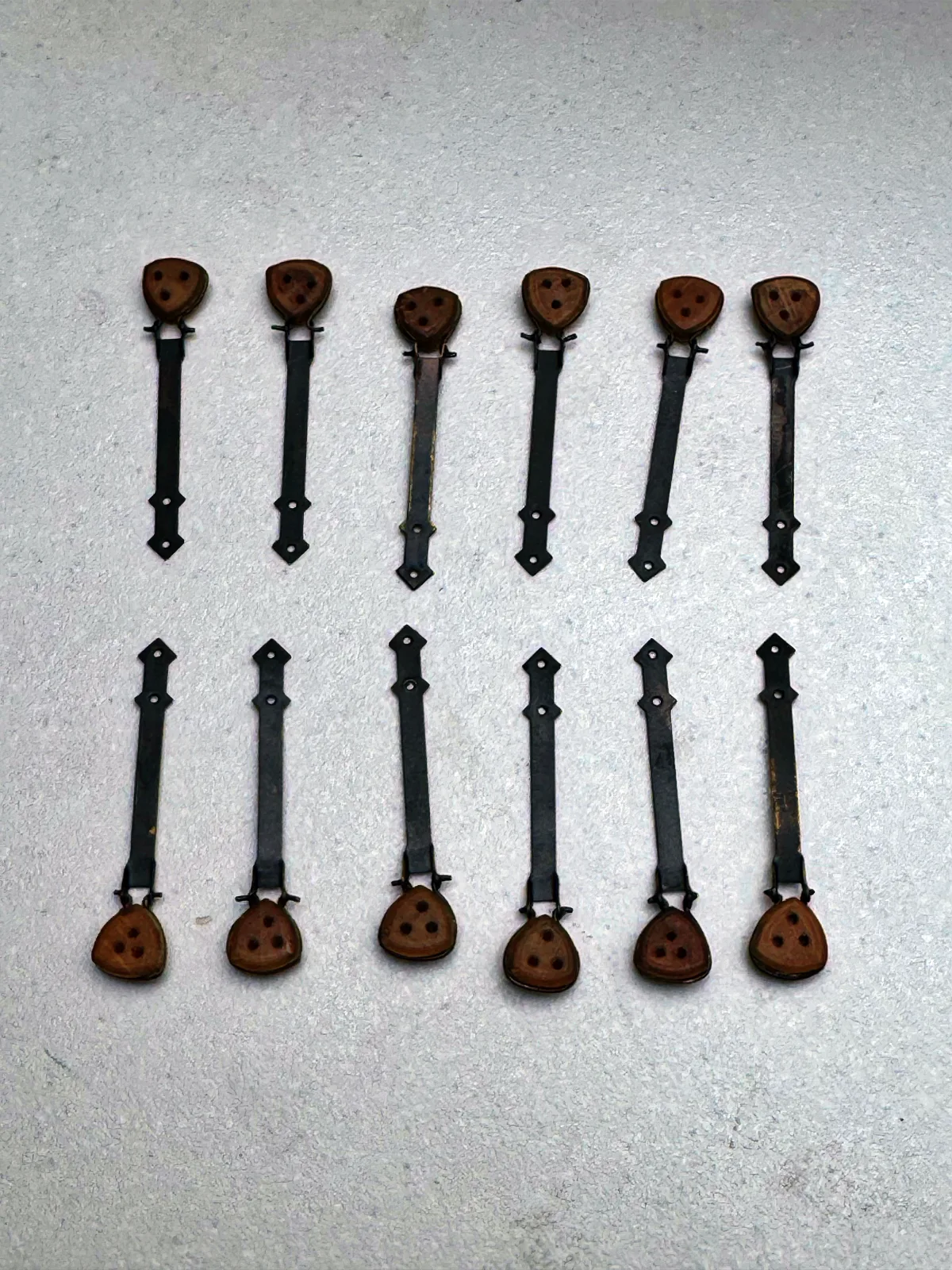
The method used to set up the shrouds differs from mast to mast. The foremast and mizzenmast shrouds are set up with lanyards and single blocks, while the main shrouds are set up with deadeyes of the characteristic triangular form used in this period. The load from the main shrouds is transferred to the hull through chainplates fitted to the channels. These metal straps embrace the lower deadeyes at their upper ends and are fastened directly to the vessel’s structural framing at their lower ends.

In this model, the main topmast shrouds do not transfer their load to the lower shrouds. Instead, they are set up with lanyards at the top, transferring the load to the crosstrees and trestletrees of the mainmast.

There are ratlines only on the main shrouds, so fitting them is not a separate epic this time, but merely a short episode: fewer than 400 ratline knots. By comparison, the Bounty required around two thousand.

The masts are now stepped, the stays and shrouds are set up, and the spars have been fitted with all the blocks required for the running rigging. We will not fit the yards at this stage. It is more convenient to attach the sails to them first, then fit the yards and sails together to the masts and bowsprit.

That will be the subject of the next part of the build log.

↑ Back to all parts

Project Specs

Model
Santa Maria
Scale
1:65
Manufacturer
Amati
Length
540 mm
Historical Year
late 15th century
Total Parts
4
Status
in progress